|
chavien.supplies@asia.com
|
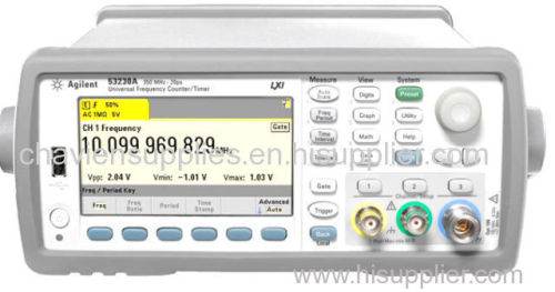
Agilent 53220A Universal Frequency Counter
| Price: | 1500.0 USD |
| Payment Terms: | T/T |
| Place of Origin: | USA |
|
|
|
| Add to My Favorites | |
| HiSupplier Escrow |
Product Detail
Agilent 53220A Universal Frequency Counter
Specifications
Agilent 53220A Universal digital Frequency Counters
Agilent 53220A Universal digital Frequency Counters
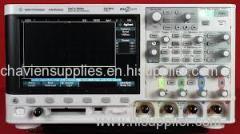
Agilent 53220A Universal Frequency Counter Timer 350 MHz . The 53220A 350 MHz universal frequency counter/timer is a two-channel frequency counter with the ability to make all the frequency and time interval measurements you depend on. An optional microwave channel can be added to measure 6 or 15 GHz.
Frequency counters are depended on in R&D and in manufacturing for the fastest, most accurate frequency and time interval measurements. The 53200 Series of RF and universal frequency counter/timers expands on this expectation to provide you with the most information, connectivity and new measurement capabilities, while building on the speed and accuracy you've depended on with Agilent's decades of time and frequency measurement expertise.
Features
Two 350 MHz input channels, plus optional third channel (6 GHz or 15 GHz)
12 digits/second resolution, 100 psec time interval resolution
LXI-C/LAN, USB, GPIB
Built-in math analysis and color, graphical display (trend and histogram)
Optional: Lithium Ion Battery
Input Channel Characteristics
Input characteristics (nom)
Channels
Standard (DC - 350 MHz) Ch 1 & Ch 2
Optional (6 or 15 GHz) Ch 3
Standard inputs (nom)
Frequency range
DC coupled DC (1 mHz) to 350 MHz (2.8 ns to 1000 sec)
AC coupled, 50 Ω 1 or 1 MΩ 10 Hz - 350 MHz
Input
Connector Front panel BNC(f). Option 201 adds parallel rear panel BNC(f) inputs 2
Input impedance (typ) Selectable 1 MO ± 1.5% or 50 O ± 1.5% ||<25 pF
Input coupling Selectable DC or AC
Input filter Selectable 100 kHz cut-off frequency low pass
10 Hz (AC coupling) cut-off frequency high pass filter
Amplitude range
Input range ±5 V (±50 V) full scale ranges
Sensitivity¾ (typ) DC - 100 MHz: 20 mVpk
> 100 MHz: 40 mVpk
Noise³ DC - 100 MHz: 20 mVpk
> 100 MHz: 40 mVpk
Input event thresholds
Threshold levels ±5 V (±50 V) in 2.5 mV (25 mV) steps
Noise reject ±5 V (±50 V) in 2.5 mV (25 mV) steps
Slope Selectable Positive or Negative
Auto-scale Acquires signal for current measurement channel,
selects range (5 V or 50 V), sets auto-level 50%
Auto-level Selectable On or Off
On: Sets auto-level (% of Vpp) operation
Occurs once for each INIT or after a timeout.
Measures signal Vpp and sets Trigger level to 50%
Off: Selectable user set level (Volts)
Minimum signal frequency
for auto level User selectable (Slow (50 Hz), Fast (10 kHz))
Minimum signal for auto
level 300 mVpp
Maximum input
50 Ω damage level 1 W
50 Ω protection threshold Will not activate below 7.5 Vpk
50 Ω internal termination auto-protects
by switching to 1 M Ω
1M Ω damage level DC - 5 kHz: 350 Vpk (AC + DC)
5 kHz - 100 kHz: Derate linearly to 10 Vpk (AC + DC)
>100 kHz: 10 Vpk (AC + DC)
Optional microwave inputs (nom)
Frequency range
Option 106 100 MHz - 6 GHz
Option 115 300 MHz - 15 GHz
Input
Connector Front panel precision Type-N(f)
Option 203 moves the input connector to a rear panel SMA(f)
Input impedance (typ) 50 Ω ± 1.5% (SWR < 2.5)
Input coupling AC
Continuous wave amplitude range
Option 106 Autoranged to +19 dBm max. (2 Vrms)
Option 115 Autoranged to +13 dBm max. (1.0 Vrms)
Sensitivity (typ) 6 GHz (Opt 106): -27 dBm (10 mVrms)
15 GHz (Opt 115):
< 3 GHz: -23 dBm
3 – 11 GHz: -27 dBm
> 11 GHz: -21 dBm
Input event thresholds
Level range Auto-ranged for optimum sensitivity and bandwidth
AM tolerance AM tolerance
Maximum input
Damage level 6 GHz (Opt 106): > +27 dBm (5 Vrms)
15 GHz (Opt 115): > +19 dBm (2 Vrms)
1. AC coupling occurs after 50 O termination.
2. When ordered with optional rear terminals, the standard/baseband channel inputs are active on both the front and rear of the
universal counter though the specifications provided only apply to the rear terminals. Performance for the front terminals with rear
terminals installed is not specified.
3. Multiply value(s) by 10 for the 50 V range.
4. Stated specification assumes Noise Reject OFF. Noise Reject ON doubles the sensitivity minimum voltage levels.
5. Assumes sine wave.
6. CW only. Assumes AM Rate > 10/gate. For Option 106, spec applies for input powers > -20 dBm; use a tolerance of 15% modulation
depth for frequencies less than 900 MHz. For Option 115, spec applies for input powers > -10 dBm.

